Power Line Maintenance Inspection Frequently Asked Questions [FAQ]
Read below the answer to some of the questions most often asked to Albatroz Engineering team:
- Why should my company acquire the equipment instead of hiring the service?
- In which scenarios is it competitive to acquire PLMI?
- Why doesn't Albatroz Engineering provide the inspection service?
- How many features can one inspect in a single pass?
- Please explain why do you claim PLMI is a flexible solution?
- How can my company integrate its current equipment into PLMI?
- What's the difference between PLMI's Track Clearance/Obstacle Detection and traditional airborne survey?
- What's the track clearance system accuracy?
- Are track clearance results consistent ?
- Which are the weather and operational constraints?
- Is it worth it to have results in real-time?
- How can the same equipment be used both on airborne and ground inspections?
- How long does it take to train the operators into using PLMI ?
- How can you assure PLMI meets my company's requirements on safety and health?
- Is the laser safe for humans?
- What's the nature and instensity of resources my company has to invest to design a PLMI solution?
- How long does it take to deliver a PLMI solution?
- Does Albatroz Engineering guarantee the aeronautical certification of PLMI?
This list only considers generic questions that are independent of particular implementations.
When a inspection framework is already in place, Albatroz Engineering integrates its PLMI solution within the existing framework, thus most of the questions derive from the specifics of integration with individual sensors, hardware and software systems and procedures.
For further information, please contact us.
1. Why should my company acquire the equipment instead of hiring the service?
Because your company will be able to inspect all the lines, all the time.
When a transmission or distribution operator sets a maintenance routine, it discovers that hiring an occasional third party service provider becomes inconvenient: there are schedule constraints, current loads on the scheduled dates are insufficient and results take too long to be delivered.
On the contrary, performing line inspection on its own or through a regular service company offers a whole year work plan and thorough coverage of extensive grids to improve overall technical quality of service. The end client can exchange lines due for inspection with short notice to meet operational conditions, ask for unforeseen inspections or simply adapt inspection plans as the year progresses.
Moreover, the client will know that the inspection team is fully focused on his/hers power lines and that these are inspected according local rules and established practices.
Sure, there are cases that call for extraordinary inspections with higher-end solutions, such as line upratings. For ordinary inspections, every inspection team visiting an over-head power line to perform routine procedures ought to carry a PLMI equipment to produce a comprehensive report on the line condition at minimum cost.
2. In which scenarios is it competitive to acquire PLMI?
Since PLMI is a custom designed solution, the actual features and value/cost ratio will vary according to individual designs. Also, operational costs - most notably, aircraft costs - vary from country to country. Finally, weather and operational constraints can put a cap on the year workload.
The main parameters that determine PLMI profitability are the value of line inspected (per kilometre) and the extension of the grid inspected per year.
Notwithstanding all the variables, Albatroz Engineering can draw some scenarios to determine viable thresholds for PLMI, which is set at break-even after two to four years.
Considering a range of scenarios of line inspections performed by helicopter, where the operational costs (aircraft and inspection crews) are proportional to the extension of the inspected grid and PLMI is the major asset investment:
- The minimum value to achieve profitability is EUR50 per km, with typical values in the range of EUR100 per kilometre.
- A minimum of 5000km (3300mi) of lines should be inspected each year to achieve profitability.
- In case of high value lines (for instance, transmission lines), profitability can be attained with as little as 3000km (2000mi) of lines inspected each year,
- In case the value lies at the bottom of the range, profitability is attained with the inspection of 15000km (10000mi) of lines or more per year.
| Notes: |
| - PLMI is competitive when it is used in a helicopter to inspect 5000km of lines or more per year. |
| - One aircraft/team can inspect up to 20000km (13280mi) of lines per year, depending on operational conditions and the degree of effort fit for maintenance inspections. |
| - The overall inspection cost should never exceed EUR150 per kilometre of line inspected. |
3. Why doesn't Albatroz Engineering provide the inspection service?
Albatroz Engineering strongly believes that local people are the best ones to inspect power lines. They know their lines, regulations and maintenance practices, therefore they can provide the most educated and insightful analysis on power line conditions, while keeping false alarms at a minimum. Thus, calling strangers to perform line inspections is bound to lead to subprime results.
Moreover, the medical and safety approval to perform professional missions inside an aircraft involves exams and training that change from country to country. It would be innefficent to maintain a group of experts approved to work in all the countries interested in PLMI.
Albatroz Engineering aims at working in collaboration with local inspectors to design the best solution within each context, but sees no purpose in taking their place as line inspectors.
In cases where the local expertise is not available, Albatroz Engineering can collaborate with local companies to perform a contract for a limited time or extension of lines.
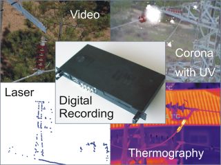
4. How many features can one inspect in a single pass?Since Track Clearance/Obstacle Detection with LiDAR is a fully automatic module, the quick answer is "how many were performed beforehand plus one". However, investing in PLMI either as a part of design of an inspection solution from scratch or as an overhaul of an existing solution, is an occasion to perform a thorough analysis of needs and possibilities, leading to solutions that improve the inspection output beyond the "previous plus one" scenario. Current implementations of Digital Recording integrate up to four features that can be acquired in one pass:
|
 |
||
|---|---|---|---|
|
Depending on local procedures, this might require a helicopter with one pilot plus an inspection team of up to three members (one per feature bar track clearance/obstacle detection).
|
|||
5. Please explain why do you claim PLMI is a flexible solution? |
|||
One of the core values of Albatroz Engineering is the design for value/cost. The architecture of PLMI embodies this need through multiple forms of flexibility:
- the same PLMI solution can be used for transmission and distribution lines. It has been successfully tested on lines from 12kV up to 500kV.
- the same PLMI solution can be operated from an helicopter and, once unmounted in two hours and mounted on an all-terrain vehicle, also used for ground inspection wherever airborne inspection is not appropriate.
- PLMI software records multiple sorts of data and outputs multiple sorts of data as well. Some are qualitative for human interpretation, such as images and vocal descriptions of hardware condition, while others are quantitative, such as locations of issues, wire temperatures or line sags.
Outputs are plastic (or flexible) in the sense they can be combined with each other and with asset data. Data can be used on statistical analysis; it can be fed into numeric models of power lines; it can used to infer contingency scenarios and variable conditions. Data can also be used to generate multimedia content for maintenance or training. - The geographical tag attached to every piece of data supports a time and space distribution of faults registered in a database. This allows maintenance team to analyse the evolution of a certain section of the line along time or, conversely, a whole grid in a limited time lapse.
An inspection database combined with an asset database will highlight specific causes or symptoms by searching common values across a population of maintenance issues. - PLMI accommodates multiple sources of data: analogue and digital cameras, sound recording, numeric data through digital channels.
- Albatroz Engineering has developed the whole software, so it is able to mould any individual PLMI solution to fit the unique needs of its clients.
| Notes: |
| PLMI is a primary airborne solution that can be also operated on the ground, if necessary. In addition to it, Albatroz Engineering is developing a different family of solutions for ground inspections only, since ground operations require a different approach and using an airborne solution on the ground would incorporate many constraints that are relevant on an airborne context only. |
| Flexibility also means that the same helicopter can be used on multiple roles, since PLMI equipment can be mounted on the field by a crew of two mechanics in a maximum of four hours (and a maximum of two hours to unmount it). |
6. How can my company integrate its current equipment into PLMI?
Albatroz Engineering developed the Digital Recording around open protocols to maximise the number of compatible data streams. Analogue video and audio are supported, digital streams can be connected through Firewire, USB or TCP/IP.
Thus, it is likely that existing cameras, or other sensors, operated by your company could be integrated into PLMI and synchronously recorded on hard disk and/or on a database.
7. What's the difference between PLMI's Track Clearance/Obstacle Detection and traditional airborne survey?
Ground survey is a very old craft that has attained a high degree of precision. Airborne surveyors strive to achieve similar levels of precision while producing very detailed 3D data from the sky. When airborne surveyors provide track clearance or obstacle detection services they do it with the same degree of precision they deliver for survey tasks.
Although Albatroz Engineering acknowledges this could be required for the project of a new power line or for the refurbishment or uprating of an existing power line, it is certainly overwhelming for routine track clearance inspection and vegetation management. After all, trees grow, and it is more valuable to know the distance to an hazardous tree with a 10cm (4in) precision today than knowing the distance with a 1cm (0.4in) three months later.
To integrate track clearance in the linemen' inspection routine, it was necessary to create a very competitive tool they could operate on their own - without calling for third party services - just like they operate an infrared camera for thermography. Moreover, it should operate automatically, since in most cases there is no free room in the aircraft for an extra inspector.
To create its Track Clearance tool, Albatroz Engineering defined its standards of accuracy and performance lower than traditional airborne surveyors'. As a consequence, mid-range sensors could be considered, while other sensors were left as an option or plainly omitted.
A side benefit of using a less powerful laser (or LiDAR) is that Albatroz Engineering only proposes eye-safe lasers so they can be operated closer to people and property without health or safety hazards.
Being closer to the ground reduces the width of the swath swept by the laser beam. Typical airborne surveyors cover a 300m swath while Albatroz Engineering's Track Clearance effectively sweeps about 100m. Naturally, if the aircraft were to fly higher above the ground, it would cover a wider swath, but then, it would render other inspections unfeasible.
Albatroz Engineering considered the whole inspection & report generation cycle in order to optimise the workflow and minimise operation costs. The major step forward in this approach is the integration of Track Clearance in the same flight used for other inspections, thus saving an extra flight.
Another step was taken to leave aside the ground team that used to perform a pre-survey and select the spots for ground GPS stations to support differential-GPS localisation. This reduces operation costs and improves aircraft operation since the helicopter moves much faster than ground teams.
A third benefit stems out of integration combined with more modest hardware: in cases where PLMI incorporates previous sensors, only minor changes to the aircraft are required. In some cases, the compact new Digital Recording replacing old tape recorders saves some room in the aircraft. In all cases, PLMI hardware is simple to mount and unmount so a dedicated helicopter is not required.
The output of Albatroz Engineering's Track Clearance yields tens of thousands of samples while traditional airborne surveyors yield millions of points. This might come as benefit - a tiny fraction of the computations to make - or as a drawback - less details in the towers, for instance. One definite benefit is that Track Clearance detects hazardous obstacles in real time!
In brief,
in case you're interested in the project of a new line or an uprating of a particular power line you might consider calling an airborne surveyor. But if you're looking for a solution for extensive track clearance and vegetation management to know all your lines, all the time, then you should definitely contact us.
Comparison summary
|
|---|
Airborne Survey |
Track Clearance |
| Millions of points | Tens of thousands of points |
| Ground swath of 300m (330yd) | Ground swath of 100m (110yd) |
| 4 to 6 points per square metre (0.4 to 0.6 points per square foot) | 4 to 15 points per square metre (0.4 to 1.4 points per square foot) at 100m swath |
| Distant video images | Close-range video |
| Differential GPS with ground station and ground team | Pseudo-differential GPS with WAAS/EGNOS without ground team |
| Dedicated flight | Integrated flight |
| Track clearance data independent from other inspections | Track clearance data merged into full-featured line report |
| 0.35m (1ft 2in) absolute localisation accuracy | 2m (6ft 6in) absolute localisation accuracy (CEP) |
| 0.01m (0.4in) relative distance accuracy | 0.05m (2in) to 0.1m (4in) relative distance accuracy |
| Flight speed above 50kt | Flight speed from 12kt to 50kt |
| Height over ground above 200m (600ft) because of health safety | Laser is eye-safe, no height over ground restrictions |
| Delayed results | Real time results |
| Fixed hardware on a dedicated aircraft | Hardware is easily removed so that aircraft can be used for other assignments |
8. What's the track clearance system accuracy?
The system accuracy depends on the laser measurement accuracy as well as on the gobal positioning accuracy. The laser measurement accuracy is defined as the distance of two targets measured in local coordinate systems during a single scan.
The range measurement accuracy depends on the laser measurement system only. For the hardware proposed on the ASLMS, the range accuracy from the sensor to target is defined by the manufacturer at 0.02m when measured against hard targets. If one estimates the accuracy between two different samples in one scan, the error associated with the rotating mirror should also be considered, but it has a negligible effect on the ranging error.
Since most practical targets are "soft" targets, such as tree leaves and ground dirt and grass, Albatroz Engineering prefers to estimate accuracy during field trials. From these, one expects accuracy to be better than 0.05m in 68% of the time (1σ) and 0.1m in 95% of the time (3σ) when the obstacles are vegetation, which is a common worst case.
The global system accuracy depends on the rigidness of the ASLMS attachment to the inspection vehicle (usually an helicopter) and, most importantly, on the accuracy of the global localisation. This is provided by GPS receivers, possibly coupled with Attitude and Heading Reference Systems (AHRS).
The initial PLMI system featured no AHRS and localisation accuracy was better than 10m in circular error precision (CEP]. The PLMI system with one GPS+AHRS sensor offers an accuracy better than 5m (CEP). Under favorable operation conditions (even terrain, smooth path and little manoeuvring) accuracy better than 3m (CEP) has been observed for whole missions.
| Notes: |
| - Multiple conductor phases are most often found in transmission lines. The conductors are kept in constant relative position by rigid spacers, whose dimension is known to the operator. |
| - Attitude and Heading Reference Systems (AHRS) are often confused with Inertial Navigation Systems (INS) or Inertial Measurement Unit (IMU). Although the concepts are not equivalent, they share most features. In particular they all provide angle and acceleration estimates. |
| - Wikipedia includes an article on Circular Error Probable (CEP). |
Accuracy is difficult to measure on site not only because objects (conductors and vegetation) move under the wind influence, but also due to variations in line current, air temperature and other lesser effects.
Given these constraints, Albatroz Engineering proposes its clients a protocol of accuracy auditing in controlled conditions. It involves the following estimates
- the largest control object (usually a cylinder) that eludes detection.
- measurement of large bodies (road widths, roof lengths)
- likelihood of detection of isolated obstacles (usually young leafless trees)
In addition to these accuracy auditing, accuracy can be estimated from the field inspections. One method is the determination of relative distances between conductors in multiple conductor phases. These are kept in constant relative position by spacers evenly distributed along the line spans.
Field results have shown that the 1σ error of the relative conductor distance is 2.5cm (1in) for two-conductor phases and 4.6cm (1.8in) for four conductor phases.
The distance accuracy is important to check compliance with regulations while the localisation accuracy is important to locate assets or objects on the ground. In most cases, the obstacles have a footprint which is either larger than the localisation accuracy (such as trees) or are non-ambiguous (such as line towers or poles), hence these thresholds should meet the requirements of maintenance inspection. The overal accuracy is a combination of both distance and localisation accuracies. In brief
- distance accuracy: better than 0.05m (1σ, 68% of cases)
- localisation accurady: better than 5m (50% of cases), can drop to 3m (50% of cases) in smooth operation conditions.
| Notes: |
| -The use of geometry analysis of the multiple conductor phases as an accuracy auditing tool has advantages... |
| - Metallic conductors (even when they are covered with oxide) are more reflective than organic surfaces such as grass or foliage |
| -Circular conductors are orthogonal to laser beam fired from all angles and orthogonal incident is the best case to return energy to the laser sensor. |
| ... and drawbacks: |
- Using the method on three or more conductor phases reveals a known laser measurement issue known as "mixed points": when two or more objects that are narrower than the laser footprint are far from the scanner and close to each other, the returned energy is a combination of the energy returned by each object and the sensor electronics might fail to discriminate between objects. In such cases, the measured distance lies between the distance to the closest and the distance to the farthest object, adding to the measurement error. |
| - Occlusions may arise due to the relative position of conductors. In such cases, a systematic error statistic will incorporate many missed objects, also adding to the measurement error. |
9. Are track clearance results consistent?
Consistency is measured by the repeatability of inspection results on the same power-lines at different moments.
Evidence from field inspection shows that repeated inspections detect clearance anomalies with distances within the error range of the system.
The distribution of clearance anomalies is also consistent in over 98% of the instances. When differences occur, they are due to the aggregation algorithms that depend on flight variables.
| Notes: |
| - When comparing two inspections of the same line, it often occurs that inspections were performed in opposite ways. In such occasions, the line is scanned from different angles and minor changes in results may occur. |
| Clearance anomalies are aggregated by clustering algorithms to prevent that a single issue (e.g. a tree) is repeated in a few consecutive anomalies. Depending on the kinematics flight parameters, the aggregation may vary, and the results are apparently different. |
10. Which are the weather and operational constraints?
Weather constraints have two major causes:
- Flight operation
- The key constraint is wind: speed, direction and variability restrain the distance and manoeuvres that can be safely performed.
Operation limits arise from sand, rain, fog and slit that impair visibility, hence performance and safety. - Sensor characteristics
- Some sensors are immune to weather constraints (or at least, their limits are far beyond the flight operation limits), while others are sensitive to weather conditions: thermal imaging results suffer from rain, LiDAR is affected by heavy fog and slit.
As a rule of thumb, PLMI hardware is at least as robust to weather as pre-existing sensors and new constraints are not expected.
11. Is it worth it to have results in real-time?
Albatroz Engineering emphasises the value of real-time results for maintenance purposes. Its benefits include
- Instant anomaly confirmation
- in a way that inspectors can collect extra data, choose the best approach to the line or tower in order to depict the issue with maximum clarity.
- Communication just after the flight
- In many cases it is not possible to communicate an urgent issue during the flight. However, as soon as the inspectors leave the aircraft they can communicate with the power line operator, sending him text and multimedia data so that he can act as soon as possible on critical issues. This is a key feature in case the inspection was ordered in the context of contingency operations.
- Mutual reinforcement of human and technology strong points
- Experienced inspectors have a profound knowledge of their grid, the nature and severity of occurrences and the time and space behaviour of every power line. However, without the best technology they can only figure out the quantitative values and, depending on the issues they can miss them altogether. Conversely, using the best technology without human craft, requires a huge effort to reproduce a fraction of the inspector insight on every line: manoeuvring to get the best depiction of an anomaly, discarding false anomalies, handling inconsistencies, etc.. Thus, Albatroz Engineering prefers to combine both, so that skilled inspectors operate with required technology to compute accurate measurements.
- Confidence building during training
- The training stage of system with a new paradigm is often awkward, especially when people don't feel the need for the innovation - they feel comfortable with their own performance - or fear that the technology will challenge their working position. Real-time results change this perception by showing people how much more they get with a little help from technology. Otherwise, people would need to go back to the lab to analyse data (imagine going back to a world where there is no digital photography and every film must be developed).
12. How can the same equipment be used both on airborne and ground inspections?
The equipment is not permanently installed on the aircraft. It consists of hardware pieces weighting about 15kg (33lbs) or less. It can that be easily mounted and unmounted in a couple of hours by mechanics in the field, with standard tools.
If the clients' equipment follows the same "mount/unmount" paradigm, all gear can be secured with straps or attached to cross bars on the ceiling of an all-terrain vehicle and ready to inspect power lines in areas where airborne inspections are not appropriate.
The installation and operation instructions consider both operations and the operators can configure the software to either scenario.
13. How long does it take to train the operators into using PLMI?
In case the line inspection team is already familiar with airborne inspections, training should take about 16 to 32 working hours, depending on the complexity of the integration with the clients' inspection hardware and information systems. Most of the training takes place in the office.
Otherwise, a similar time budget should be included in the overall training program.
14. How can you assure PLMI meets my company's requirements on safety and health?
PLMI is individually developed for each individual client. Therefore, the requirements of safety and health will be embedded in the system specification and system design.
In addition to that, all equipment is procured from reputed manufacturers that abide to RoHS requirements.
15. Is the laser safe for humans?
All Albatroz Engineering lasers are Class 1, hence safe for the eyes of operators and bystanders.
| Notes: |
| - For an introduction to laser safety, please refer to laser safety on Wikipedia. |
| - IEC 60825 standard defines the safety norm, including Class 1 lasers. |
16. What's the nature and intensity of resources my company has to invest to design a PLMI solution?
The level of commitment depends on the complexity of the modules required and the difference between the existing solution and the PLMI-enhanced solution.
For companies with an already established airborne inspection routine, designing a new solution is a matter of assessing what should be kept and what should be changed in the procedures.
In case the client is not familiar with helicopter inspections, then a preparation must be made to establish the needs on aircraft, crew, operation procedures and its limits and contingencies.
The design of a new user interface, both for airborne operations and for interfacing existing information systems on the ground can also require significant effort, but the outcome is usually worth every hour dedicated to it since the efficiency and quality of work are dependent on it.
All issues considered the design of a new PLMI solution should require the equivalent of 1 person between two to six weeks, in case the client is familiar with airborne inspection routines and six to twelve weeks, otherwise.
17. How long does it take to deliver a PLMI solution?
The answer depends on the individual features each client requires and the interchange of information and specification iterations.
As a rule of thumb, a minimum of two months for specification, three months for development and one month for testing should be considered.
18. Does Albatroz Engineering guarantee the aeronautical certification of PLMI?
No. Aeronautical certification is a process whose complexity, requirements and length varies significantly across the world, thus certification should be regarded as a local process.
Notwithstanding, given its experience in the European certification under EASA jurisdiction, Albatroz Engineering can collaborate with its clients in this region. Also, due to similarities between FAA and EASA rules, Albatroz Engineering can support any companies doing the certification with the appropriate technical documentation.
Moreover, all processes and products are established with the specific concern to obtain aeronautical certification from FAA and/or EASA.
| Notas: |
| - European Aircraft Safety Agency (EASA) - www.easa.europa.eu - is the agency responsible for aeronautical certification within the European Union. The agency often delegates some of its authority to national aeronautical agencies. |
| - The United States of America Federal Aviation Agency - www.faa.gov - and EASA share a significant acquis on aeronautical safety, hence a product certified in one of the regions is likely to be certifiable on the other. |
| - Many other countries accept FAA or EASA approved technical documents as a part of their internal certification procedures, somewhat accelerating the certification process. |
GIM Frequently Asked Questions
- How does GIM compare to other 3D modeling technologies?
- What's the purpose of the image?
- How fast can GIM travel while modeling?
- What's the resolution of the 3D models? And the density of points per square meter?
- Can GIM be used indoors too?
1. How does GIM compare to other 3D modeling technologies?
The most common solutions for three dimension (3D) reconstruction and modeling of outdoor environments uses high quality-high cost equipments designed for survey, architecture, reverse engineering and other high precision applications. The key equation to this activity is the following:
LiDAR + GPS = 3D Model
One of the characteristics of these solutions is the long and thorough calibration of localisation and orientation of equipments that must preced data acquisition, which may also take long. As a consequence, the number of acquisition points is reduced to a minimum.
By mounting the sensor system in a vehicle or in a mobile platform, there is a significant reduction on the model accuracy. On the other hand, one gains in flexibility, speed of aquisition and access to new viewpoints. Moreover, the equipment and the operation procedures are less demanding since modeling algorithms acommodate larger measurement errors.
Albatroz Engineering identified the opportunity for competitive 3D modeling applications for outdoor scenarios or installations from mobile platforms.
2. What's the purpose of the image?
Image is not part of the key equation shown above but it is very useful to improve the likelihood of 3D models and to help inexperienced users to recognise the original environments when looking at 3D models. That's why Albatroz Engineering prefers the equation:
LiDAR + Image + Motion + GPS = GIM = Textured 3D Model
3. How fast can GIM travel while modeling?
Acquisition speed depends on the application. The Roman Galleries of Lisbon were modeled at a speed of a few centimeters per second while railway models were created at160kmph (44,4m/s or 106mph).
4. What's the resolution of the 3D models? And the density of points per square meter?
Again, it depends on the application. Albatroz Engineering dispões de equipamentos e sensores de diferentes especificações e faz o software de medição e modelação para todos eles. Por esse motivo, está capacitada para criar uma solução à medida de cada problema.
5. Can GIM be used indoors too?
Yes.
While the system was designed for outdoors and big size scenarios, some modeling devices can be mounted on a aluminum mono-rail and used in confined environments. Such is the case of the Roman Galleries of Lisbon that are about 2,2m wide and 2,5m high. In some sections, height above ground is less than 1m.
| ©2014 Albatroz Engineering Inc. All rights reserved. | site map | webmaster |